• One manometer with brake ½ inch .
  • Up link ½ inch.
  • Down link ½ inch.
  • Up isolation valve.
  • Down isolation valve.
  • One glass tube.
  • One level gauge protection, ajustable

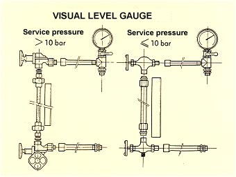
In conformity with the beside drawing,

  • Mount the different parts to join the upper leg of the level gauge to the vessel.
  • Mount the bottom leg.
  • Place the different seals and nuts on the glass tube.
  • Put in place the glass tube, by moving slowly the two legs of the level gauge, the tube must penetrate into the legs with more than a centimeter into each valve.
  • Slide the rubber seals around the glass tube and lock the nuts to obtain a perfect water/air tightness.

Alignment of the two valves, and the glass tube must be perfect.

  • Mount the level gauge protection, and ajust the length to avoid separation of the level gauge legs and a dislocation of the glass tube.
  • Proceed to the preinflation, check for leaks, and proceed to the commissioning of the tank.

The tank, on which this equipment is mounted is ready to be used, but pumps stopped. It contains a certain water and air quantity at the static pressure.

  • Open the upper valve ( gas circuit ).
  • Slowly open the bottom valve ( water circuit ). The fluid level must go up and be stabilised ( commonly the water level must be stable between 1/2 and 2/3 of water ). .
  • Draw a mark on the glass tube, shut the two valves and empty the glass tube level gauge.

At a given pressure, always corresponds a given water level in the vessel.

At regular intervals, check for leaks. If the stabilised water level is above the mark on the glass tube, open the bleed cock on the bottom part of the tank. If you obtain water, the bladder is pierced, if no water, there is leak of air on the tank or the level gauge - you have to find and solve it.

WHEN THE VESSEL IS OPERATING, THE LEVEL GAUGE HAS TO BE PERMANENTLY EMPTY ( UP AND DOWN VALVES CLOSED ) !

PLEASE CONSULT US, OUR STUDIES ARE FREE OF CHARGE