LE RESERVOIR MASSAL - Société Anonyme au Capital de 6.250.000F

CHEMIN DES SEPT FONTS - BP 117 - 34302 AGDE CEDEX 02 - FRANCE - TEL. 33 (0)4 67 94 79 11 - FAX. 33 (0)4 67 21 06 89

E-mail : MASSAL@wanadoo.fr Web : http://www.massal.com

R.C.S. Béziers B 345 355 622 000 19 - NAF 282 A - N° TVA CEE FR 81 345 355 622

SIRET 345 355 622 000 19 - A P E : 2408


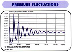
Pressurized systems subjected to Pump Stoppages, Valves Closures, etc ..., may be suffering from surge phenomenna during transients due to changes of flow velocities.


It is an hydraulic phenomenum caused by velocity changes of the fluid being transported within the pipeline. It is characterised by a noise, but above all, by pressure changes which range from total vaccum ( cavitation ) to important over-pressures. They may seriously damage the system and its components. If surge is detected through a surge analysis, it is necessary to cancel or limit this phenomenum by installing an adequate protection device. There are many of such devices and the choice is dictated by the individual conditions of each system.


LE RESERVOIR MASSAL has acquired a reputable software with which it carries out simulations for itd Customers to define if there is a problem or no, and when necessary to recommend the most economical cure ( protection ) for the said problem.

DATA TO BE SUPPLIED :

  • The profile of the pipeline or network under investigation, especially the chainge and elevations of the points of importance ( Air Valve, Wash out, etc ... )
  • The total system discharge ( Pump, Duty Curves and Moment of inertia ).
  • Pump Suction level.
  • Discharge level.
  • Pipe characteristics ( Diameter, Materiel, etc...).
  • List and Characteristics of the Hydraulic Accessories/Devices installed in the system ( Valve, NRV, Air Valves, etc....).


The system data supplied by the client, is entered in the software ; then, the software simulate steady state, and transient conditions.


Once the steady state calculations have taken place, the transient analysis is undertaken and by iteration, by altering the "VO" ( Volume of air in the vessel during steady state ), the outpout data will give us :
  • The Volume of the vessel
  • The minimum pressure at each node
  • The minimum Piezometric Level of each Node
  • The maximum Pressure at each Node.
  • The maximum Piezometric Level of each Node.


These results make it possible to determine :

  • The vessel's Volume
  • The vessel's Service Pressure
  • The Outlet Characteristics
  • The need for auxillary devices such as Non Return Valves


The "HYDROPAN" range of LE RESERVOIR MASSAL may be used with : - One or several pumps.
- To maintain pressure in a network where the pump have variable speeds or in a sprinkler fire system, for exemple.
- Any application where there is a need to give the network some elesticity.
The principe is simple and rests on " MARIOTTE's Law ", when the relation between the volume ( V ) and the pressure ( P ), because :

P x V x Gamma = P' x V' x Gamma = CONSTANTE.


The calculations are done in absolute value ( Gauge + 1 bar )

Pp = Precharge pressure P1 = Pump start pressure P2 = Pump stop pressure V Air at Pp x Pp = V Air at P1 x P1 = V Air at P2 x P2 = CONSTANTE

V Air at P1 - V Air at P2 = Volume disponible of water.

  • PRESSURE MAINTENANCE IN GENERAL

    There are no general rule to define the volume of such a vessel.
    The purpose of such a vessel is to maintain the network pressure, when the pump(s) is stopped.
    The volume of this type of vessel is calculated in order to prevent the pump(s) to start ans stop too often, to compensate leakages.
    The purpose of this vessel can be dual cater for pressure maintenance, as well as surge protection.

  • BOOSTER VESSELS and VARIABLE SPEED PUMPS

    The calculation covers the pump duty from Qo to Qmin.

  • BOOSTER VESSEL and FLOW CONTROLS

Where the start and stop of the pump(s) is controlled by flowmeter, there is no need for a booster vessel.

  • BOOSTER VESSEL and PRESSURE SWITCHES

Where a Jockey pump, controlled by pressure switches, is used to cater for small demands, then a booster vessel is recommended. It will be sized as above. Booster vessels are important, when pumps controlled by pressure switches have start/stop cycles greater than 6 to 10 per hour, depending on the Manufacturer's recommendations.

The pump start and pump stop duty points must be available.
  • OPERATION
  1. The pump starts.
  2. The pump supplies the network directly and vessel fills when demand becames inferior to the pump's discharge.
  3. When the system reaches the maximum pressure setting, the pump stops..
  4. The booster vessel maintains the system pressure between the given settings and caters for system's demand.
  5. The pump re-starts when the minimum pressure setting is reached again.
  • SIMPLIFIED CALCULATION FORMULA
The main parameters are :
  1. Vt = Vessel Total Volume ( in liters )
  2. Qo = Average Pump Discharge ( in liters / seconde )
  3. P1 = Minimum Pressure ( in bar absolute )
  4. P2 = Maximum Pressure ( in bar absolute )
  5. Pp = Precharge Pressure ( Usually P1 - 0,5 bar ) maxi 5 to 7 bar depending with bladder type
  6. N = Number of admissible start/stops per hour.
Vt = 900 x Qo x P1 x P2
-----------------------------
N x ( P2 - P1 ) x Ppg

In this case, the pump start/stop cycles are controlled by pressure switche(s).
The purpose of the booster ( regulation ) vessel is to limit the number of the pump's start/stop cycles within the limits recommended by the pump Manufacturer.

All pump duties must be known.

  • OPERATION

The first pump starts, depending on demand, it assures the network's supply or refills the vessel as well. If demand is greater than the first pump duty, the second starts and so on.... When demand diminishes, the pump switches off, one by one, until the last pump fills the vessels completely before stopping when the maximum pressure setting is reached. after each cycle, it is recommended to swap the sequence of pumps startings

  • CALCULATIONS

There no simple mathematical formulae. LE RESERVOIR MASSAL as developped a software to cater for this solution. All our customer have access to this service. All we need is the hydraulic data relating to your system.